
We offer booster coils for duct mounting and low-flow applications.

WATER BOOSTER COIL -
TYPE WC
Primary Surface
Round seamless copper tubes are mechanically expanded into the fin collars of the secondary surface. The mechanical expansion provides a permanent metal-to-metal bond for efficient heat transfer. Tubes are staggered in the direction of airflow and only RETURN BENDS are used to ensure NO reduction in tube wall thickness in the bend radius associated with hairpin tubes.
Secondary Surface
Corrugated aluminum or copper plate-type fin that is die-formed. Fin collars are full-drawn to provide accurate control of fin spacing and maximum contact with tubes.
Headers
(When furnished) are seamless copper with die-formed holes that provide a parallel surface to the coil tube for strong brazing joints. All circuiting is designed to gravity-drain with the coil mounted vertically and tubes running horizontally.
Connections
Copper MPT.
Casing
Die-formed flanges with stacking flanges on top and bottom. Intermediate tube supports are supplied on coils over 44” fin length with an additional support every 42”.
Testing and Performance
All coil assemblies are leak tested under water with dry air at 315 PSIG. Performance is AHRI Certified™ to Standard 410. Coil performance ratings are calculated using Temtrol AHRI Certified™ selection software.
HOT WATER BOOSTER COIL - TYPES Z, A
Primary Surface
Round seamless copper tubes are mechanically expanded into the fin collars of the secondary surface. The mechanical expansion provides a permanent metal-to-metal bond for efficient heat transfer. Tubes are staggered in the direction of airflow and only RETURN BENDS are used to ensure NO reduction in tube wall thickness in the bend radius associated with hairpin tubes.
Secondary Surface
Corrugated aluminum plate-type fin that is die-formed. Fin collars are full-drawn to provide accurate control of fin spacing and maximum contact with tubes.
Headers
(When furnished) are seamless copper with die-formed holes that provide a parallel surface to the coil tube for strong brazing joints. All circuiting is designed to gravity-drain with the coil mounted vertically and tubes running horizontally.
Connections
Copper male pipe thread (MPT).
Casing
Casing Type Z is galvanized steel with 1½” die-formed flanges to permit easy mounting. Casing Type A is galvanized steel with die-formed bar for “slip & drive” duct connections.
Casing Type A option: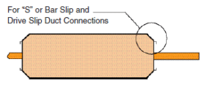
Testing and Performance
All coil assemblies are leak tested under water with nitrogen at 315 PSIG.
COIL OPTIONS
Water Booster Coil – Type WC
Rows: 1, 2
Fin Height: 6” to 18”
Fin Length: 6” to 48”
Fin Spacing:
1/2” – 8 to 14 fins per inch
5/8” – 6 to 14 fins per inch
Fin Thickness ALUMINUM:
1/2” – 0.006”
5/8” – 0.008” or 0.010”
Fin Thickness COPPER:
1/2” – 0.006”
5/8” – 0.006” or 0.008” or 0.010”
Tube O.D.Tube Thickness:
1/2” – 0.017” or 0.025”
5/8” – 0.020” or 0.025” or 0.035” or 0.049”
Tube Spacing Face x Row:
1/2” – 1.25”/1.083”
5/8” – 1.50”x1.299”
Casing:
16 or 14 GA Galvanized Steel
304, 316 Stainless Steel
Max. Std. Operating Conditions: 250 PSIG 300° F
Hot Water Booster Coil – Types Z, A
Rows: 1, 2
Fin Height: 6”, 9”, 12”, 15”, 18”
Fin Length: 6” to 48” (on 3” increments)
Fin Spacing:
1-row 10 fins per inch
2-row 8 fins per inch
Fin Thickness ALUMINUM: 0.008”
Tube O.D. Tube Thickness: 5/8” 0.020”
Tube Spacing Face x Row: 1.50”x1.299”
Casing:
Type Z 16 GA
Type A 20 GA Galvanized Steel
Max. Std. Operating Conditions: 250 PSIG 300° F


